Saturday, August 6, 2016

Best Practices and Securing Cisco IOS

Best Practices and Securing Cisco IOS


Everyone has different views on hardening IOS, and while I do not claim to be an expert, these are the practices that I commonly use when bringing up a new device. If you see something I missed, please leave a comment and I’ll add it to the list and send the credit your way. I’ve also included general best practices that I follow that fall outside of the security realm. This is in no way a complete list of best practices, or a complete steb-by-step guide to hardening an IOS device.

Base SSH and AAA

Before we get too far, we need to setup the basics. In order to enable SSH, we need to set a hostname, domain suffix, and generate an RSA key. Next we’re going to set some values that should be self explanatory.
The next section states that we’re going to lock out logins for 5 minutes if we have 4 unsuccessful attempts inside of 2 minutes. After an unsuccessful attempt, we’re delaying for 2 seconds, and on any failure or success we log.
The last 2 sections are a basic configuration for AAA. First we define a level 15 user named admin with a password of cisco. Then, we define our login and exec policies to use the local login methods. This is just a base line of the AAA configuration as once it’s moves to production you’ll add it to your TACACS/ACS server, right??? I also recommend changing your local admin/backup in case TACACS is down name from admin to something… more obscure. Captain? General? SquidBoy? Anything other than the normal admin, root, administrator, and etc.

!
hostname Rooter
ip domain-name routerjockey.com
crypto key generate rsa modulus 2048
ip ssh time-out 120
ip ssh version 2
ip scp server enable
!
login block-for 300 attempts 4 within 120
login delay 2
login on-failure log
login on-success log
!
username admin privilege 15 secret 0 cisco
!
aaa new-model
aaa authentication login default local-case
aaa authorization exec default local if-authenticated
!

Line Security

Next we’re going to configure the lines used to gain console or VTY access. For the console line, I ensure logging synchronous is turned on to prevent mid-command interruption from logging messages. Transport preferred none disables the default behavior of attempting to open a telnet session to input that isn’t matched by the IOS command parser. Changing the escape-character to 3 allows us to use <ctrl>+C instead of <ctrl>+<shift>+6.
On our aux line, I’m always sure to disable exec, and as a fallback, set the exec-timeout to 1 second. I also like to disable output on the line using transport output none.
Now, probably the most important is securing your VTY lines. The ACL VTY-in is defined by only allowing devices that absolutely need access. This then applied via the access-class command to the vty lines. Again, logging synchronous, escape-character 3, and transport preferred none are used. I also disable telnet access by only allowing input via SSH.
!
ip access-list extended VTY-in
 remark == Network Engineering VPNs
 permit ip 10.255.200.0 0.3.0.31 any
 remark == Network Management Servers
 permit ip 192.168.42.0 0.0.0.255 any
!
line con 0
 logging synchronous
 transport preferred none
 escape-character 3
line aux 0
 exec-timeout 0 1
 no exec
 transport output none
line vty 0 15
 access-class VTY-in in
 logging synchronous
 transport preferred none
 transport input ssh
 escape-character 3
!

Services

As with any best practice, any unnecessary services should be disabled. Most of these are rarely used for any legitimate purpose, but can be used to launch attacks that are otherwise prevented by packet filtering. The following is a list of services that should be disabled unless in use.
  • IP Source Route should be disabled to prevent implicit tunneling attacks.
  • Packets that contains IP options must be punted, which can lead to high CPU utilization. IP options can also alter the path that traffic takes through the network, potentially allowing it to subvert security controls. Unless you have specific reasons, this traffic should be dropped. (This can break RSVP)
  • HTTP and HTTPS servers – do I really need to explain what these are?
  • TCP/UDP Small services such as echo, discard, daytime, chargen should be disabled. Although they can be protectd by an ACL, it would be best to just disable them. (The default since IOS 12.0)
  • Password Encryption is just a best practice, the encryption used is a very simple Vigenère cipher and only protects from teh casual observer.
  • The service tcp-keepalive-in and service tcp-keepalive-out global configuration commands enables the device to send TCP keepalives for TCP sessions, thus ensuring that the remote device is accessible and that half-open/orphaned connections are closed.
  • DHCP, the Dynamic Host Configuration Protcol, best to leave this disabled if not in use.
  • BootP, the Bootstrap Prototol used for auto configuration.
  • Finger is a legacy protocol used for status and user information. Disabled by default since 12.1(5)
  • The ip identd command returns accurate information about the host TCP port; however, no attempt is made to protect against unauthorized queries.
  • Many engineers recommended disabling CDP. Although, I only do this in places where my network touches external networks. (The command to globally disabled CDP is not listed below. Therefore it is no cdp run – alternatively the interface command no cdp enable can be used to disabled it interface by interface.
  • The Link Layer Discovery Protocol (LLDP) is an IEEE protocol similar to CDP. Except that LLDP allows interoperability between Cisco and non-Cisco devices that do not support CDP.
  • Service Config should be disabled unless you’re loading configurations from the network.
  • MOP or the Maintenance Operation Protocol is a legacy service used for utility services such as uploading and downloading system software, remote testing and problem diagnosis.
  • Packet Assembler/Disassembler or PAD service is used on X.25 networks.
no ip source-route
ip options drop
no ip http server
no ip http secure-server
no service tcp-small-servers
no service udp-small-servers
service password-encryption
service tcp-keepalives-in
service tcp-keepalives-out
no service dhcp
no ip bootp server
no ip finger
no ip identd
no service config
no lldp run global
no mop enabled
no service pad

Login Banner

In some areas it can be impossible to prosecute and illegal to monitor malicious users unless they have been notified that they are not permitted to use the system. One method to provide this notification is to place this information into a banner message that is configured with the Cisco IOS software banner login command. The following is a slightly edited example from sans.org.
!
banner login ^
************************************************************************
You have logged on to a COMPANY proprietary device. 

This device may be used only for the authorized business purposes 
of COMPANY. Anyone found using this device or its information for
any unauthorized purpose may be subject to disciplinary action 
and/or prosecution. Have a nice day! :)
************************************************************************
^
!

SNMP, Logging, and NTP

Monitoring, monitoring, monitoring. One of the most important aspects of keeping your users happy that often gets pushed out of priority. When configuring SNMP, I’m sure your Network Management System (NMS) will appreciate you setting your SNMP location string, many use this to group systems. Whenever possible, please start using SNMPv3, an example for v2 and v3 is included (both of them use an ACL to provide additional security)
Syslog allows you to stream your logging messages to a remote server for aggregation, search ability and base line tracking. While I could’ve put the service timestamp command in with the rest of the service configuration, I thought it belonged here. This tells our router to use timestamps down to the millisecond in local time, and to also print the current timezone.
And last, but not least, please be good about setting up your time zones, and NTP destinations across your organization. Trying to dig through logs with different time zones, and unsynchronized time is a huge PITA.
! 
snmp-server location HQ
ip access-list 60 remark == SNMP RO
ip access-list 60 remark -ServerName
ip access-list 60 permit 192.168.42.23
ip access-list 60 deny ip any any log
!
! SNMP v2
snmp-server community r0u73rj0ck3y RO 60
!
! SNMP v3 <-- More Secure
snmp-server user snmpv3user PRIVGROUP v3 auth md5 authpassword priv 3des privpassword access 60
!
logging host 192.168.42.42
service timestamps log datetime localtime msec show-timezone 
!
ntp server 10.1.1.10 preferred
ntp server 10.2.1.10
!

Misc

The last couple of commands here are part best practices, and part convenience. The first command enables Cisco's Configuration Generation Performance Enhancement feature which greatly speeds up polling for current configuration data. Previous to this command NVGEN always had to query the entire system and could generate only a total configuration. This feature allows for caching of interface configuration information in system memory.
The second set of commands here configures your time zone, and sets up automagic DST based on the rules here in the states. For those of you outside the US, please use the following command. clock summer-time zone recurring [week day month hh:mm week day month hh:mm [offset]]
parser config cache interface
!
clock timezone EST -5 0
clock summer-time EDT recurring

Wednesday, June 15, 2016

Configuring Static NAT on a Cisco ASA Security Appliance

http://blog.router-switch.com/2013/04/configuring-static-nat-on-a-cisco-asa-security-appliance/

Two of the most common forms of network address translation (NAT) are dynamic port address translation (PAT) and static NAT.
PAT is the many-to-one form of NAT implemented in many small office and home networks where many internal hosts, typically using RFC 1918 addresses such as 192.168.0.0/24, share a single external address on the public Internet. Static NAT is a one-to-one mapping which is used when an internal host needs to be accessible from the public Internet or some other external network.
Here we will explain how to configure static NAT to make an internal Web server accessible from an external network. The same concept applies when you want to make any internal server accessible from an external network, whether it’s a Web server, a mail server, an FTP server, or any other type of server or device.
This is based on ASA software Version 9.0(1) and applies to Version 8.3 and later.
Use the following diagram with this documentation. This diagram uses RFC 1918 addresses. In the real world, the outside interface would most likely be configured with a registered, public address.
configure static NAT on a Cisco ASA01
There are four steps involved in enabling static NAT:
1. Create the network object and static NAT statement. A network object must be created identifying the internal host. Within the network object, you must also create a static NAT statement to identify the outside interface, its IP address, and the type of traffic to be forwarded: object network InternalHost host 192.168.102.5 nat (inside,outside) static interface service tcp 80 80.
2. Create a NAT statement identifying the outside interface. Note that, in the static NAT statement above, the use of the term interface tells NAT to use whatever address is on the outside interface. The first use of 80 identifies the originating port number. The second use of 80 identifies the destination port number.
3. Build the Access-Control List. Build the Access-Control List to permit the traffic flow (this statement goes on a single line): access-list OutsideToWebServer permit tcp any host 192.168.102.5 eq www.
4. Apply the ACL to the outside interface using the Access-Group command: access-group OutsideToWebServer in interface outside. This is the complete configuration:
configure static NAT on a Cisco ASA02
When successfully implemented, this configuration will permit a host on the outside network, such as the public Internet, to connect to the internal Web server using the address on the ASA’s outside interface.
Configuring the ASA with Multiple Outside Interface Addresses
It is not possible to assign multiple IP addresses to the outside interface on a Cisco ASA security appliance. It is possible, however, to configure the ASA to forward different outside addresses to different hosts on the inside network.
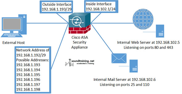
For example, you have a /29 block of addresses assigned by your ISP. Also, suppose you have a mail server using POP3 and SMTP and a Web server using HTTP and HTTPS on the inside network. You want each of the servers to be reachable via different outside addresses. You can configure static NAT to accomplish this (see diagram, and again, in the real world the outside interface would probably be configured with registered, public addresses instead of the RFC 1918 addresses shown here).
configure static NAT on a Cisco ASA03
The steps are similar for single-address static NAT configuration:
1. Configure network objects. Configure a network object for each internal host with a static NAT static statement specifying the outside address to be used and the service types (port numbers) to be forwarded. These identify the internal hosts, the desired outside IP address, and the type of service to be forwarded. (The exclamation marks are for formatting to improve readability and are not required for the configuration.)
object network WebServer-HTTP
host 192.168.102.5
nat (inside,outside) static 192.168.1.194 service tcp 80 80
!
object network WebServer-HTTPS
host 192.168.102.5
nat (inside,outside) static 192.168.1.194 service tcp 443 443
!
object network MailServer-SMTP
host 192.168.102.6
nat (inside,outside) static 192.168.1.195 service tcp 25 25
!
object network MailServer-POP3
host 192.168.102.6
nat (inside,outside) static 192.168.1.195 service tcp 110 110
Note that in the above configurations the host statement identifies the internal server (192.168.102.5 is the Web server and 192.168.102.6 is the mail server). The NAT statement identifies the external address used to forward the specified packets to the internal host.
2. Configure Access-Control Lists to permit the traffic flows. This Access-Control List permits the traffic flows against the security levels (each access-list statement goes on a single line).
access-list OutsideToInside permit tcp any host 192.168.102.5 eq 80
access-list OutsideToInside permit tcp any host 192.168.102.5 eq 443
access-list OutsideToInside permit tcp any host 192.168.102.6 eq 25
access-list OutsideToInside permit tcp any host 192.168.102.6 eq 110
3. Apply the Access-Control List to the outside interface with an access-group statement.
access-group OutsideToInside in interface outside
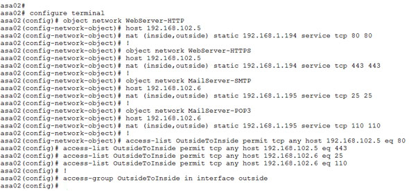
Here is the complete configuration:
configure static NAT on a Cisco ASA04

Thursday, May 19, 2016

How to Clear IPSec VPN Remote Peer on Cisco IOS

How to Clear IPSec VPN Remote Peer on Cisco IOS

The following command clears the crypto sessions for a remote IKE peer. You can use context sensitive help ? to find other options.

Syntax

clear crypto session remote IP_ADDRESS

Example:

clear crypto session remote 1.1.1.1

Thursday, April 21, 2016

Details of Account Lockout Settings and Processes

With the account lockout feature enabled, access to the account is denied when the number of logon attempts that did not work exceeds the LockoutThreshold registry value (the account lockout threshold) in a specified amount of time. A locked-out account cannot be used until it is reset by an administrator or until the lockout duration for that account expires.
Account Lockout is disabled on default installations of Windows NT Server 4.0, Windows 2000, and Windows Server 2003 domains. Account lockout operation is enabled after the domain administrator enables settings in the default domain policy. The policy settings remain enabled when you upgrade domain controllers to a later version of an operating system.
Although the Group Policy Object Editor appears to support account lockout and password policy in each organizational unit, these settings actually occur across the domain; you must define the settings on the root organizational unit for the domain. Microsoft recommends that you define account lockout and password policies in only one Group Policy object (GPO) for every domain (in the Default Domain policy settings).

Password Policy Settings

The first step that you should use to secure your network is to enforce password policy settings. When you implement a secure password policy, you may not need to implement the account lockout feature.

Password Complexity

Passwords, by default, can include any combination of characters; passwords can also be blank. Microsoft recommends that you require the use of complex passwords to help ensure that passwords provide the best security possible. These complex passwords are much more resistant to attack than blank or simple passwords.
To enforce password complexity in your organization, you can enable the Password must meet complexity requirements security setting. The complexity requirements enforced by this setting are stored in Passfilt.dll. In Windows 2000 operating systems and later, Passfilt.dll is built into the operating system. In Windows NT Server 4.0, you must add the Passfilt.dll file to the operating system to achieve the same results. Passfilt.dll is included in Windows NT Server 4.0 Service Pack 2 and in later service packs.
By default, complex passwords enforced by Passfilt.dll have the following properties:
  • Do not contain all or part of the user's account name.
  • Contain characters from three of the following four categories:

    • English uppercase characters (A through Z).
    • English lowercase characters (a through z).
    • Base-10 digits (0 through 9).
    • Non-alphanumeric (for example, !, $, #, %). extended ASCII, symbolic, or linguistic characters.
noteNote
Depending on your environment, using extended ASCII, symbolic, or linguistic characters in passwords can have unexpected results. It is highly recommended that you test these characters before using them in production.

When implementing this policy, it is recommended to inform your users of the change in policy so that a smooth transition can take place from a simple password to a complex password. Otherwise, users may be confused by the new password criteria and circumvent security to avoid the difficulty.
You can create and register your own custom password filter if you want to modify the complexity requirements enforced in the security setting.

Password History

You can use the Password History setting to prevent users from repeatedly using the same password. When you use the password history feature, a user is prevented from using passwords that they used in the past, up to the number of passwords that you specify. You can configure Windows to retain between 0 and 24 passwords by using the Password History feature. Microsoft recommends that you set the password history to the maximum value to help ensure the least amount of password reuse by users.
In the Windows 2000 Server family and later, the location of the password history is in the Default Domain policy settings at Computer Configuration\Windows Settings\Security Settings\Account Policies\Enforce Password History.
Valid non-zero values are between 1 and 24. The default value is 24 for domain controllers running a member of the Windows Server 2003 family, 3 for domain controllers running a member of the Windows 2000 family, and 0 for all other Windows operating systems.

Minimum Password Length

You can use the Minimum Password Length setting to decrease the chances that a password can be discovered by a malicious user. For more information about the Minimum Password Length setting, see "Understanding Password Complexity" in this document.
In versions of Windows 2000 operating systems and later, you can change the Minimum Password Length setting in the Group Policy MMC, in the Default Domain policy settings at Computer Configuration\Windows Settings\Security Settings\Account Policies\Password Policy\Minimum Password Length.
An administrator can set the value between 0 and 14 characters. Each additional character increases the total possible password permutations. However, if you set the value to 0, blank passwords are not permitted.
Valid non-zero values are between 1 and 14, with a default value of zero.

Maximum Password Age

You can use the Maximum Password Age setting to limit the time for which a given password is valid. This decreases the odds of being able to crack a password. For more information, see the example in the Passwords section in this document.
In the Windows 2000 family and later, the Maximum Password Age setting is located in the Group Policy MMC, in the Default Domain policy at Computer Configuration\Windows Settings\Security Settings\Account Policies\Password Policy\Maximum Password Age.
This setting determines the period of time (in days) that a user can use their password before the computer requires the user to change it. You can set passwords to expire in between 1 and 999 days, or you can specify that passwords never expire by setting the number of days to 0.
Valid non-zero values are between 1 and 999, with a default value of 42.

Minimum Password Age

You can use the Minimum Password Age setting to preventing users from repeatedly changing passwords until the user is able to use their original password, if you enforce the Password History setting.
When you use the Minimum Password Age setting, you prevent the circumvention of password expiration and help to assure unique passwords.
The Minimum Password Age setting determines the period of time (in days) that a password must be used before the user can change it. You can set the value to between 1 and 999 days, or allow immediate changes by setting the number of days to 0.
Configure the Minimum Password Age setting to be a number that is larger than 0 if you want the Enforce Password History setting to be effective. If you do not set a minimum password age, users can repeatedly cycle through passwords until they are able to use an old favorite password. This could allow users to circumvent established password policy.
The Minimum Password Age setting is located in the Group Policy MMC, in Computer Configuration\Windows Settings\Security Settings\Account Policies\Password Policy.
Valid non-zero values are between 1 and 999, with a default value of one for domain controllers and zero for other computers.

Account Lockout Settings

You can set the Account Lockout settings in the Active Directory Users and Computers MMC by using the procedure in this section.
noteNote
The value that you set for LockoutDuration cannot be a value that is less than OberservationWindow.

  1. Click Start, click Settings, click Control Panel, double-click Administrative Tools, and then double-click Active Directory Users and Computers.
  2. In the console tree, right-click the domain on which you want to set a Group Policy object.
  3. Click Properties, and then click the Group Policy tab.
  4. In Group Policy Object Links, click Default Domain Policy or create and name your Group Policy object, and then click Edit.
  5. In the console tree, double-click Computer Configuration, double-click Windows Settings, double-click Security Settings, double-click Account Policies, and then click Account Lockout Policy.
  6. In the details pane, right-click the policy setting that you want, and then click Properties.
  7. If you are defining this policy setting for the first time, click Define this policy setting.
  8. Click the options that you want, and then click OK.

ObservationWindow

The ObservationWindow setting (also known in Group Policy as the Reset account lockout counter after setting) is the number of minutes after which an accounts badPwdCount registry value is reset. You can use the ObservationWindow setting to help mitigate lockout issues that are initiated by users. When you enable this setting, the bad password attempt is removed from the server after a period of time.
Valid non-zero values are between 1 and 99999, with a default value of 30.

LockoutDuration

The LockoutDuration setting (also known in Group Policy as the Account lockout duration setting) is the amount of time, in minutes, that account lockout is enforced on an account that has exceeded the LockoutDuration registry value, measured from the time of lockout. If you set the LockoutDuration registry value to 0, the account is permanently locked out until either an administrator or a user who has a delegated account resets the account. If the administrator or a delegated user account does not unlock the account, the operating system unlocks the account after the number of minutes that you set in the LockoutDuration registry value. Non-zero values for the LockoutDuration registry value reduce the administrative overhead of unlocking accounts by having them unlocked automatically; however, non-zero values do not provide the added security of user validation before the account is restored.
Valid non-zero values are between 1 and 99999, with a default value of 30.

LockoutThreshold

The LockoutThreshold setting (also known in Group Policy as the Account lockout threshold setting) is the number of times that the user, computer, service, or program can send a bad password during logon authentication before the account is locked out. Account lockout occurs when the badPwdCount registry value is equal to or exceeds the LockoutThreshold value. You can adjust the LockoutThreshold value to prevent both brute force and dictionary attacks, but you can set the value too low to capture user error and other non-attack errors. Administrators often set this value too low (3 through 5), which causes a large number of account lockouts because of user error, program caching by service accounts, or issues with networking clients. If you set the LockoutThreshold value to 0, no account lockouts occur on the domain.
Valid non-zero values are between 1 and 999, with a default value of zero.

Account Lockout Values

Account lockout registry values are described in this section. These values store the information that you need to track account lockout information.
noteNote
These values are maintained by the operating system, so you should not manually modify them.

badPasswordTime

The badPasswordTime value stores the last time that the user, computer, or service account submitted a password that did not match the password on the authenticating domain controller This property is stored locally on each domain controller that is in the domain. A value of 0 means that the last incorrect password time is unknown. For an accurate value for the user's last incorrect password time in the domain, you must query each domain controller that is in the domain; the largest one is the accurate value. For more information, see the "LockoutStatus.exe" section in this document.
noteNote
The badPasswordTime registry value is not replicated between domain controllers. This attribute, however, is reported to the PDC operations master.

badPwdCount

The badPwdCount value stores the number of times that the user, computer, or service account tried to log on to the account by using an incorrect password. This value is maintained separately on each domain controller in the domain, except for the PDC operations master of the accounts domain that maintains the total number of incorrect password attempts. A value of 0 indicates that the value is unknown. For an accurate total of the user's incorrect password attempts in the domain, you must query each domain controller and use the sum of the values. For more information, see the "LockoutStatus.exe" section in this document.
noteNote
The badPwdCount registry value is not replicated between domain controllers. This registry value, however, is reported to the PDC operations master.

ntPwdHistory

The ntPwdHistory registry value contains the password history for the user in Windows NT Server 4.0 one-way function (OWF). Both Windows 2000 and the Windows Server 2003 family use the Windows NT Server 4.0 OWF. This property is used by only the operating system. Note that you cannot obtain the password from the password in OWF form.

Other Settings that Affect Account Lockout

This section describes another setting that affect account lockout behavior. While the setting is focused on authentication, it is closely tied with account lockout policy.
You can set the authentication settings in the Active Directory Users and Computers MMC by using the procedure in this section.
  1. Click Start, click Settings, click Control Panel, double-click Administrative Tools, and then double-click Active Directory Users and Computers.
  2. In the console tree, right-click the domain on which you want to set a Group Policy object.
  3. Click Properties, and then click the Group Policy tab.
  4. In Group Policy Object Links, click Default Domain Policy or create and name your Group Policy object, and then click Edit.
  5. In the console tree, double-click Computer Configuration, double-click Windows Settings, double-click Security Settings, double-click Local Policies, and then click Security Options.
  6. In the details pane, right-click the policy setting that you want, and then click Properties.
  7. If you are defining this policy setting for the first time, click Define this policy setting.
  8. Click the options that you want, and then click OK.

ForceUnlockLogon

The ForceUnlockLogon setting (also known as Interactive logon: Require Domain Controller authentication to unlock workstation controls the behavior of a computer running Windows 2000, Windows XP or the Windows Server 2003 family when the computer is unlocked by a user.
  • With a value of 1 (or Enabled, in Group Policy), unlocking the computer also performs a synchronous logon to the domain to verify user authenticity. This option is slower than allowing cached authentication because it requires network-based authentication.
  • With a value of 0 (or Disabled, in Group Policy), cached information is used to verify the users identity. When the verification is successful, the user is logged on. Windows then performs an asynchronous logon to the domain in the background. This means that the user can still unlock a computer when the account is unlocked.
  • Valid values are 0 and 1, with a default value of 0.
For additional information about unlocking a workstation, see the following articles:

Replication and Account Lockout

Account lockout relies on the replication of lockout information between domain controllers to ensure that all domain controllers are notified of an accounts status. In addition, password changes must be communicated to all domain controllers to ensure that a user's new password is not considered incorrect. This data replication is accomplished by the various replication features of Active Directory and is also discussed in this section.

Immediate Replication

When you change a password, it is sent over Netlogon's secure channel to the PDC operations master. Specifically, the domain controller makes a remote procedure call (RPC) to the PDC operations master that includes the user name and new password information. The PDC operations master then locally stores this value.
Immediate replication between Windows 2000 domain controllers is caused by the following events:
  • Lockout of an account
  • Modification of a Local Security Authority (LSA) secret
  • State changes of the Relative ID (RID) Manager

Urgent Replication

Active Directory replication occurs between domain controllers when directory data is updated on one domain controller and that update is replicated to all other domain controllers. When a change in directory data occurs, the source domain controller sends out a notice that its directory store now contains updated data. The domain controller's replication partners then send a request to the source domain controller to receive those updates. Typically, the source domain controller sends out a change notification after a delay. This delay is governed by a notification delay. (The Windows 2000 default notification delay is 5 minutes; the Windows Server 2003 default notification delay is 15 minutes.) However, any delay in replication can result in a security risk for certain types of changes. Urgent replication ensures that critical directory changes are immediately replicated, including account lockouts, changes in the account lockout policy, changes in the domain password policy, and changes to the password on a domain controller account. With urgent replication, an update notification is sent out immediately, regardless of the notification delay. This design allows other domain controllers to immediately request and receive the critical updates. Note, however, that the only difference between urgent replication and typical replication is the lack of a delay before the transmission of the change notification. If this does not occur, urgent replication is identical to standard replication. When replication partners request and subsequently receive the urgent changes, they receive, in addition, all pending directory updates from the source domain controller, and not only the urgent updates.
When either an administrator or a delegated user unlocks an account, manually sets password expiration on a user account by clicking User Must Change Password At Next Logon, or resets the password on an account, the modified attributes are immediately replicated to the PDC emulator operations master, and then they are urgently replicated to other domain controllers that are in the same site as the PDC emulator. By default, urgent replication does not occur across site boundaries. Because of this, administrators should make manual password changes and account resets on a domain controller that is in that user's site.
The following events are not urgent replications in Windows 2000 domains:
  • Changing the account lockout policy
  • Changing the domain password policy
  • Changing the password on a computer account
  • Domain trust passwords
For additional information about urgent and immediate replication, see "Urgent Replication Triggers in Windows 2000" in the Microsoft Knowledge Base.

Single User Object On Demand Replication

In the Windows 2000 family, when an administrator resets and immediately expires a user's password on a domain controller in site A (so that the user is given a new password but forced to change it when the user first logs on), the logon may still succeed when the user logs on with that new password in site B. This occurs because the domain controller chains to the PDC operations master during authentication. However, the users password change may not replicate correctly because domain controllers in site B do not yet have the reset password. This occurs because there is replication latency between sites.
An update is available for Windows 2000 that changes this behavior. For more information to help change this behavior by implementing an "on-demand" replication scheme, see "You Cannot Change Your Password After an Administrator Resets It" on the Microsoft Knowledge Base. The updated replication scheme allows the domain controller to contact the PDC operations master to request an update of the user object that failed authentication because of an incorrect password. This helps to ensure that the authenticating domain controller receives the most current user account information as quickly as possible.

Mixed Environments with Windows NT Server 4.0 and Active Directory Domain Controllers

If servers that are running Windows NT Server 4.0 and earlier are in the domain, account lockout is not a dependable security feature.
For example, a Windows NT Server 4.0, Enterprise Edition, backup domain controller (BDC) may authenticate a user, even though the account is marked as locked out on a domain controller that is running Windows NT Server 4.0 and earlier. Also, Windows NT Server 4.0, Enterprise Edition, BDCs cannot unlock an account. The server that is running Windows NT Server 4.0, Enterprise Edition, can increment the bad password count when the user logs in with an incorrect password. That server can then report the increment to the other domain controller. However, the Windows NT Server 4.0, Enterprise Edition, BDC does not send this information to the domain controller that is running Windows NT Server 4.0 and earlier if the user logs on with the correct password. Because of this, the bad password count is not reset after the successful logon attempt.
The account lockout feature of Microsoft LAN Manager is not compatible with the account lockout feature on computers that are running Windows NT Server 4.0 and earlier. The domain controller that is running Windows NT Server 4.0 and earlier does not replicate any account lockout information to a LAN Manager BDC. If the account is marked as locked out on the Windows NT Server 4.0 and earlier domain controller, the LAN Manager BDC may still validate the user. The LAN Manager BDC displays the account lockout policy as set to "Never," even in a domain running Windows NT Server 4.0 and earlier where account lockout is enabled.
For these reasons, you should consider ensuring that all domain controllers in your network are running Windows 2000 or the Windows Server 2003 family. This is the only way to ensure that account lockout is enforced consistently across your network.

Wednesday, March 9, 2016

Easy Remote Client VPN Solution with a Cisco ASA

Easy Remote Client VPN Solution with a Cisco ASA

I’ve posted an article on Client VPN setup using OpenVPN and I noticed I didn’t have one regarding Cisco ASA. A Cisco ASA being a very common Security Appliance used by small and large companies. This article will cover how to setup a standard remote client VPN utilizing IPsec as the crypto carrier. Cisco also has their own proprietary remote client VPN solution called AnyConnect. I will be posting an article after this one on how to set an AnyConnect solution up and include what the differences are between it and the standard IPsec remote client VPN contained in this article.
A remote client VPN is something very common in workplace now-a-days. It allows users to appear as if they are on the company’s internal network over an insecure medium(e.g. Internet, untrused Network, etc). It does so by using IPsec. IPsec is a tried and true Layer 3 securing technique that requires both parties involved to mutually authenticate each other before passing traffic.
A few things to keep in mind regarding remote client VPNs.
  • First, a subnet is required for client’s to be put on when successfully authenticated and authorized via the remote client VPN. This can be the same subnet as one already existing on your network or a separate one with a firewall in-between The later being best in practice and security.
  • Secondly, deciding on split-tunneling vs all-tunneling. The difference being on the client would you like all traffic to be forced across the tunnel or allow clients to communicate with both their local network and the networks on the otherside of the VPN. For best practice and security, all-tunneling is recommended.
  • Third, Access Lists and tunneled networks. Here we will decided what Remote VPN users will have access to other networks. We will also, in the case of split-tunneling, create an access-list of what networks to tunnel for the Remote VPN user.
  • Fourth, provisioning standard network services for VPN user’s. Remote VPN user’s will need a default gateway, DNS servers, domain suffix, an address pool, proxy settings, etc.

Configuring the Server Side (Cisco ASA):

  1. First Step: Create an Address Pool for VPN clients.
    Decided on the subnet you will be assigning to remote VPN clients. For this article I will choose 172.21.1.0/24, staring at .10 and ending at .250.
  2. Next step: Make an additional ACL to identify the traffic we would like the remote client to know about on the other side of the tunnel (For Split-Tunneled scenarios).
  3. Moving on: We have to create an identify NAT because our VPN traffic communicating with our Proected networks will travers two different interfaces on the Cisco ASA. We will not be performing an NAT manipulation, but the statement is required because of Cisco ASA standard security policy when traversing traffic between different interfaces.
  4. VPN Attributes: Let’s set up group-policy to tie together all the attributes we are going to send to the remote client when they connect.
    Let’s step thru this:
    • ClientVPN_GroupPolicy {internal/external} — Where to get attributes from? Internal = from this ASA, External = from external server like RADIUS or Cisco ACS
    • ClientVPN_GroupPolicy attributes — First we have to create a new group policy whcih will push down to the cilent all the network services we want to assign them.
    • banner value {your text} — This is not technically needed, however I like it because it gives the user a pop-up from their VPN software that they have successfully connected.
    • vpn-idle-time {min} — Helpful to terminate VPN connections that are idle for too long.
    • vpn-session-timeout {min} —
    • vpn-filter value {your ACL} — This is where you set the ACL with the networks your VPN Network is allowed to communicate with others inside your network.
    • vpn-tunnel protocol {ikev1} — Tells client to use ikev1 to establish a connection.
    • ipsec-udp {enable/disable} — This will enable IP NAT traversal, which is 99% of the time needed. If you don’t enable it, only one client will be able to connect in from the same remote network at a time. See What is IPsec NAT-Traversal
    • split-tunnel-policy {tunnelspecified/tunnelall} — Sets the split-tunneling policy, if any.
    • split-tunnel-network-list {standard ACL} — what networks on far side to tell the client about.
    • dns-server value {dns servers} — Specify the DNS servers to have your remote VPN clients use.
    • default-domain value {windows domain name} — Supplied to client for DNS suffix.
    • split-tunnel-all-dns {enable/disable} — Tells client whethers to ask far end of the tunnel for DNS reslution or use local network DNS. Best practice is to enable this and force remote VPN clients to always ask far end for DNS resolution.
    • address-pools value {IP pool object} — Where to get IPs for remote VPN clients from.
    • ipv6-address-pools {IP pool object/none} — IPv6 pools? Nah.
    • NOTE:For more information and other attributes, see the Cisco documentation here.
  5. Proxy settings?: We can also try to push down Web Proxy settings to Internet Explorer using the following


  6. IPSec Phase1: Here we set up Phase 1 to be used by this IPsec tunnel.


    NOTE: The Cisco VPN Client v5 will match the first IKEv1 policy you have for Phase 1. Don’t forget to enable it on the outside interface!
  7. IPSec Phase 2: Continuing on in building our Transport tunnel, we now have to create a Crypto Map (in this case Dynamic), and a Transform set.


    NOTE: dynamic-map is used here because the remote endpoint’s address could be anything. Unlike other IPsec tunnels where we know both endpoint address are predetermined and it is part of the Security Association (SA). Specifying the dynamic-map keyword tells the ASA not to perform peer IP validation after initiating the tunnel. For more info on static tunnels read my other post here.
  8. Last Step: Putting it all together with a Tunnel Group object.


    NOTE: Type remote-access = tells ASA this is a remote-access tunnel and not a Site-to-Site tunnel. We also bind what Group Policy to use with this tunnel here. Don’t forget to set the Phase1 pre-shred-key here!!
  9. Creating users within the LOCAL user-table on your Cisco ASA

Configuring the Client Side

Windows — Using Cisco VPN Client
  1. Download software here
  2. Install (duh!)
  3. Configuration:
    windows cisco VPN
    windows cisco VPN2
    windows cisco VPN3
  4. Wahoo!!

Friday, January 8, 2016

Packet Tracer 6.1 - HSRP Configuration

What is HSRP ?

HSRP (Hot Standby Router Protocol) is a redundancy protocol for setting up a fault-tolerant default gateway in a LAN environment. This is a Cisco proprietary protocol. The standard protocol is VRRP (Virtual Router Redundancy Protocol)
The primary router with the highest configured priority operates as a virtual router with a virtual gateway IP address. It responds to the ARP request from PC or servers connected to the LAN with the MAC address 0000.0c07.acXX where XX is the HSRP group ID (converted to an hexadecimal value). If the primary router should fail, the Cisco router with the next-highest priority available in the LAN segment would take over the gateway IP address and answer ARP requests with the same mac address, thus achieving transparent default gateway fail-over.


HSRP in Packet Tracer 6.0

HSRP is a new feature of Packet Tracer 6.0 . This protocol can be configured on every Cisco router available in Packet Tracer as well as on Cisco Catalyst 3560 layer 3 switch.
The following IOS commands are available :
  • standby  <0-4095> ip        Enable HSRP and set the virtual IP address
  • standby  <0-4095> preempt   Overthrow lower priority Active routers
  • standby  <0-4095> priority  Priority level
  • standby  <0-4095> timers    Hello and hold timers
  • standby  <0-4095> track     Priority Tracking


HSRP configuration using Cisco 2911 ISR routers

Packet Tracer 6.0.1 - HSRP topology example with Cisco 2901 ISR routers

Two network are configured for this tutorial :
  • Network 192.168.1.0/24
    • Router0 : 192.168.1.2 (GigabitEthernet 0/0)
    • Router1 : 192.168.1.3 (GigabitEthernet 0/0)
  • Network 192.168.2.0/24
    • Router0 : 192.168.2.2 (GigabitEthernet 0/1)
    • Router1 : 192.168.2.3 (GigabitEthernet 0/1)
Two HSRP groups are configured on the ISR routers :
  • HSRP Group 1 :
    • IP address : 192.168.1.1
    • Router0 with priority 120 (preemption enabled)
    • Router1 with HSRP default priority (100)
  • HSRP Group 2 :
    • IP address : 192.168.2.1
    • Router0 with priority 120 (preemption enabled)
    • Router1 with HSRP default priority (100)

Routers configuration

Router0 configuration Router1 configuration
interface GigabitEthernet0/0
 ip address 192.168.1.2 255.255.255.0
 duplex auto
 speed auto
 standby version 2
 standby 1 ip 192.168.1.1
 standby 1 priority 120
 standby 1 preempt
!
interface GigabitEthernet0/1
 ip address 192.168.2.2 255.255.255.0
 duplex auto
 speed auto
 standby version 2
 standby 2 ip 192.168.2.1
 standby 2 priority 120
 standby 2 preempt
interface GigabitEthernet0/0
 ip address 192.168.1.3 255.255.255.0
 duplex auto
 speed auto
 standby version 2
 standby 1 ip 192.168.1.1
!
interface GigabitEthernet0/1
 ip address 192.168.2.3 255.255.255.0
 duplex auto
 speed auto
 standby version 2
 standby 2 ip 192.168.2.1

Preemption is configured on Router0 using the standby X preempt commands. This router will always assume HSRP active state when it's online and if it has the highest HSRP priority in the network. The same configuration without the standby x priority 120 configuration on Router0 does not work and Router1 assumes the active state because it has a higher IP address configured.


Testing the configuration

Packet Tracer 6.0 - HSRP active router (ISR 2911) with preemption enabled
Packet Tracer 6.0 - HSRP standby router (ISR 2911) with 2 groups

Router0 is active for both HSRP groups. Both routers detected each other correctly but the priority seems to be wrong (Standby router is 192.168.1.3, priority 120 should be Standby router is 192.168.1.3, priority 100 on Router0)

Testing HSRP configuration is Packet Tracer 6.0.1 (ping, tracert, arp)

Ping, traceroute and arp commands issued on Laptop0 confirms that the configuration is working. The IP packets are transiting through Router0 (192.168.1.2)

Known bug

HSRP can be configured the same way on Cisco 3750 multilayer switch vlan interfaces in Packet Tracer 6.0.1.

interface Vlan100
 ip address 192.168.1.2 255.255.255.0
 standby version 2
 standby 1 ip 192.168.1.1
 standby 1 preempt
!
interface Vlan200
 ip address 192.168.2.2 255.255.255.0
 standby version 2
 standby 2 ip 192.168.2.1
 standby 2 preempt